
Featured Pipeline Components & Flange Series (Top Line)
Factory-direct forged components manufactured under strict ISO 9001 quality systems complying with ASME, EN, and JIS standards.
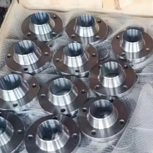
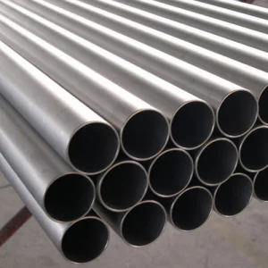
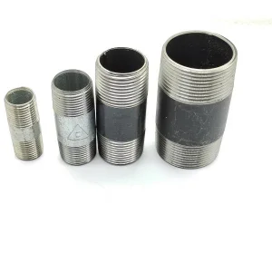
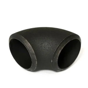
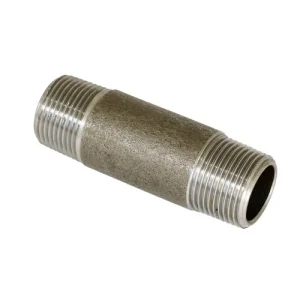
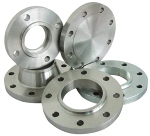
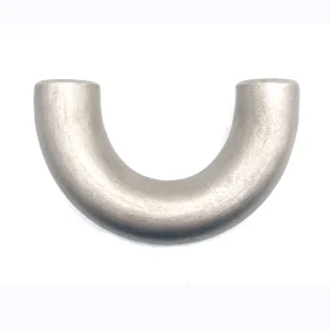
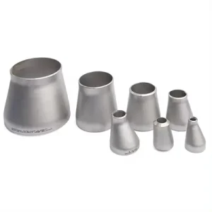
1. Architectural Mechanics & Operational Purpose of Blind Flanges
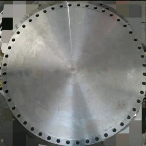
In modern industrial piping design, a blind flange (BL Flange) serves as a critical mechanical boundary component designed to blank off a section of pipe, a valve, or a pressure vessel opening. Unlike weld neck, slip-on, or socket weld flanges, a blind flange contains no center bore. It operates as a solid pressure barrier, bearing the full hydrostatic thrust caused by internal system pressures and ambient thermal loads.
Blind flanges play a fundamental role in routine maintenance, pressure testing, line flushing, and system expansion. When integrated into complex petrochemical refineries or offshore platforms, they provide a positive, leak-tight seal that allows operators to safely isolate downstream equipment without shutting down the entire continuous production circuit.
Pressure Boundary Isolation
Designed in strict compliance with ASME B16.5 and B16.47 standards, blind flanges withstand extreme tensile stress and bending moments induced by high-pressure fluid media up to Class 2500 and PN400.
Integrity & Hydrostatic Blanking
Provides absolute containment during hydrostatic testing procedures. Blind flanges act as rigid end closures, enabling precise integrity validation of newly installed or retrofitted piping loops.
Versatile Structural Adaptation
Available with various facing types—such as Raised Face (RF), Flat Face (FF), and Ring Type Joint (RTJ)—matching exact gasket dynamics and seating stress distributions.
Engineering Insight: Finite Element Analysis (FEA) in Blind Flange Stress Distribution
Under internal pressure, a blind flange experiences maximum bending stress at its geometric center and maximum shear stress near the bolt circle. Unlike hubbed flanges, the absence of a central opening requires thicker plate dimensions to limit central deflection ($\delta$). This deflection must remain within micro-inch limits to prevent gasket unseating and subsequent fugitive emissions.
2. Material Science & Metallurgical Standards Matrix
Selecting the optimal alloy grade for blind flanges requires evaluating mechanical yield strength, pitting resistance equivalent number (PREN), operational temperature envelopes, and fluid chemistry (such as $H_2S$, $CO_2$, and chloride concentrations).
| Material Category | Standard Grades | Operational Temperature Range | Primary Industrial Applications |
|---|---|---|---|
| Carbon Steel | ASTM A105, A350 LF2 Class 1/2, A694 F42–F70 | -46°C to 425°C | Oil & gas transmission, steam systems, general industrial utilities. |
| Austenitic Stainless Steel | ASTM A182 F304/304L, F316/316L, F321, F347 | -196°C to 815°C | Chemical processing, cryogenic LNG, pharmaceutical, food & beverage. |
| Duplex & Super Duplex | ASTM A182 F51 (S31803), F53 (S32750), F55 | -50°C to 280°C | Offshore platforms, subsea manifolds, seawater desalination, acid gas lines. |
| Alloy & High-Temp Steel | ASTM A182 F11, F22, F91, F92 | -29°C to 650°C | High-pressure power generation, thermal power boilers, hydrocrackers. |
| Nickel Alloys & Clad | Inconel 625, Hastelloy C276, Monel 400, Clad A105+N06625 | Cryogenic to 1000°C | Extreme sour gas service (NACE MR0175/ISO 15156), nuclear power, PTA plants. |
3. China Industry 4.0: Supply Chain Resilience & Manufacturing Excellence
China's industrial pipe fitting and flange sector has evolved from labor-intensive forging workshops into automated, smart-factory ecosystems. Centered in world-renowned hubs such as Cangzhou, Hebei, manufacturers utilize end-to-end digital integration—from raw billet induction heating to 5-axis CNC machining and automated non-destructive testing (NDT).
Closed-Die & Ring-Rolling Forging Automation
Modern Chinese forging operations employ high-tonnage hydraulic presses integrated with robotic arms. Closed-die forging ensures optimal grain flow alignment along the flange profile, boosting impact toughness and eliminating internal voids or gas inclusions often found in cast alternatives.
Digital Twin Heat Treatment Protocols
Heat treatment—including normalizing, quenching, tempering, and solution annealing—is tracked via real-time SCADA systems. Precise temperature control ensures uniform metallurgical phase distribution (e.g., achieving a 50/50 austenite-ferrite ratio in duplex stainless steel).
4. Macro-Industry Solutions & Global Field Deployments
Blind flanges must adapt to specialized environmental demands. Below is a breakdown of technical configurations engineered for global industries:
Petrochemical & Hydrocarbon Refining
High-temperature crude distillation units require ASTM A105 or A182 F11 blind flanges equipped with spiral wound gaskets (316L/Graphite). For sour gas cracking lines, material selection transitions to NACE MR0175-compliant alloys to resist hydrogen-induced cracking (HIC).
Cryogenic LNG Infrastructure
Liquefied Natural Gas operating at -162°C demands exceptional low-temperature notch toughness. ASTM A350 LF2 Class 2 carbon steel or A182 F316/316L stainless steel blind flanges undergo Charpy V-notch testing down to -196°C to guarantee structural ductile-to-brittle transition protection.
Offshore Marine & Subsea Pipelines
Exposed to severe marine splash zones, subsea blind flanges utilize Super Duplex (F53/F55) or Inconel 625 weld-overlay clad carbon steel. These components withstand pitting corrosion, crevice corrosion, and hydrostatic pressures exceeding 300 bar.
5. Technical Roadmap & Future Innovations
The industrial piping sector is shifting toward decarbonization, green hydrogen transit, and digital asset tracking. The technological evolution of blind flanges reflects these critical industry updates:
1. Hydrogen-Ready Metallurgical Formulations
As global energy networks transition to blended and pure hydrogen distribution, standard carbon steels face risks of hydrogen embrittlement. Next-generation blind flanges utilize ultra-clean steel melting techniques (VAD/AOD processes) with low sulfur ($S \le 0.002\%$) and low phosphorus ($P \le 0.005\%$), combined with micro-alloying additives (Titanium/Niobium) to trap atomic hydrogen safely.
2. Smart Digital Flanges (IoT-Integrated Sealing)
Industry 4.0 integration introduces "Smart Blind Flanges" equipped with embedded piezoelectric strain sensors and fiber-optic temperature sensors. These sensors transmit real-time data on bolt preload relaxation, localized flange rotation, and micro-leakages to plant SCADA systems, enabling predictive maintenance before catastrophic gasket failure occurs.
3. Automated Weld Overlay Cladding Technology
Rather than solid nickel alloy construction, advanced manufacturing utilizes hot-wire GTAW/SAW clad overlaying. Applying a 3mm to 5mm layer of Inconel 625 or 316L onto an A105 carbon steel base provides equal corrosion protection at 40% of the material cost.
4. Green Steel Forging & Net-Zero Manufacturing
Leading Chinese exporters are transitioning toward electric arc furnace (EAF) steelmaking powered by renewable energy. Direct Reduced Iron (DRI) techniques significantly lower the carbon footprint of forged blind flange products destined for environmentally regulated markets like the EU.
6. Procurement Best Practices & Regulatory Compliance
To avoid project delays, unexpected downtime, or safety risks, engineering procurement teams must enforce stringent quality assurance standards when sourcing blind flanges from overseas manufacturers.
Material Test Report Verification (EN 10204 3.1/3.2)
Insist on complete mill traceability certified under EN 10204 Type 3.1 (or Type 3.2 third-party witnessed by agencies such as DNV, Lloyd's Register, or TÜV). Verify heat numbers, chemical composition ladle analyses, mechanical yield/tensile strength, and Charpy impact values.
Dimensional Inspection & Facing Finish Integrity
Dimensional tolerances must strictly mirror ASME B16.5 or EN 1092-1. Raised face serrations require continuous spiral or concentric grooves machined to an average roughness ($Ra$) of 3.2 to 6.3 micrometers (125 to 250 micro-inches AARH) for standard spiral wound gaskets.
Global Certification & Standard Compliance
Ensure manufacturers hold active accreditations: Pressure Equipment Directive (PED 2014/68/EU), ASME Boiler and Pressure Vessel Code (Section VIII), Canadian Registration Numbers (CRN), and NACE MR0175/ISO 15156 compliance for sour service.
Comprehensive Piping Equipment Showcase (Bottom Line)
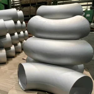
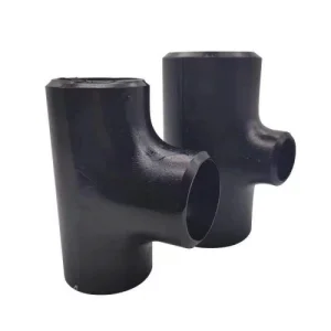
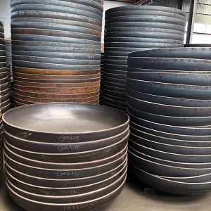
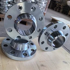
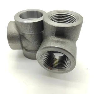
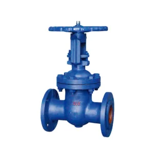
Explore complete piping system accessories, elbows, tees, caps, and industrial valves supplied alongside forged blind flanges.

7. Comprehensive Engineering FAQ & Technical Troubleshooting
frequently asked technical questions addressed by senior pipeline design specialists and quality management auditors.
According to ASME Boiler and Pressure Vessel Code Section VIII Division 1 (UG-34), the minimum required thickness ($t$) for an unstayed flat head or blind flange is determined by the formula: $t = d \sqrt{(C \times P) / (S \times E) + (P / (S \times E))}$, where $d$ represents the effective gasket diameter, $P$ is the internal design pressure, $S$ is the maximum allowable stress value of the material at design temperature, $E$ is the joint efficiency factor, and $C$ is a structural attachment factor (typically 0.30 for bolted blind flanges). Corrosion allowance ($CA$) must be added to the calculated thickness.
Raised Face (RF) flanges feature a 1/16" (1.6mm) or 1/4" (6.4mm) raised surface mated with non-metallic or semi-metallic gaskets (e.g., spiral wound gaskets). RF blind flanges are suited for applications up to Class 600. Ring Type Joint (RTJ) blind flanges contain a precisely machined metallic groove designed to seat a solid metal ring gasket (Oval or Octagonal R, RX, or BX type). RTJ configurations are engineered for extreme pressure applications (Class 900 to Class 2500) and elevated temperatures, delivering a metal-to-metal seal.
Tapped blind flanges are modified blind flanges featuring a central or eccentric female NPT or BSPP threaded port (typically 1/2" to 2" NPT). They are specified when engineers require a temporary or permanent connection point for pressure gauges, vent lines, drain valves, chemical injection quills, or hydrostatic testing connections without cutting or welding adjacent piping.
ASME B16.5 covers pipe flanges and flanged fittings in nominal pipe sizes from NPS 1/2 through NPS 24 in Pressure Classes 150 through 2500. ASME B16.47 covers large-diameter steel flanges from NPS 26 through NPS 60. ASME B16.47 is divided into Series A (MSS SP-44) and Series B (API 605). Series A flanges are thicker, heavier, and carry higher external bolt loads, making them standard for general piping pipelines. Series B flanges feature smaller bolt circles and lighter dimensions, optimized for compact pressure vessel applications.
Proper bolt loading requires a star-pattern crossover torquing sequence executed in multiple stages: 30%, 60%, and 100% of final target torque value, followed by a final rotational pass. Anti-seize lubricants must be accounted for in torque calculations via nut factors ($K$). Hydraulic bolt tensioning is recommended for high-pressure blind flanges (Class 900+) and nominal sizes exceeding 12 inches to ensure uniform gasket compression and eliminate flange rotation.
For sour service applications containing wet hydrogen sulfide ($H_2S$), carbon steel blind flanges (such as ASTM A105 or A350 LF2) must adhere to NACE MR0175 restrictions to avoid Sulfide Stress Cracking (SSC). Key requirements include a maximum carbon equivalent ($CE \le 0.43\%$), controlled material hardness below 22 HRC (Rockwell C), post-weld heat treatment (PWHT) if modified by welding, and HIC/SOHIC testing according to NACE TM0284.